Automatic rotor resistance starter circuit diagram Electrical schematic – motor starting system – resistance stator Starter slip rotor starters resistors electricaltechnology
automatic rotor resistance starter | 3 stage resistance | explained in
Rotor starter diagram stator electricalworkbook Rotor resistance starter circuit diagram What is motor starter? types of motor starters
Resistance starting: definition, working principle, pros & cons
A "media to get" all datas in electrical science...!!Starter rotor Motor rotor circuit wound power electrical diagram control schematic induction bank wiring automatic hoist ac resistors used step electronics engineeringRotor starter resistance diagram circuit motor.
What is induction motor drive? explanation & starting methodsRotor resistance starter Rotor resistance starterLiquid resistance starter circuit diagram.

Self start 3-φ induction motor slip-ring wound rotor starter
Resistance starter rotor motor electrical slip fig stepsLiquid resistance starter circuit diagram Resistance rotor starter starters types electricalRotor resistance starter control circuit diagram.
Starter rotor automaticAutomatic rotor resistance starter circuit diagram Resistance stator starter electrical figSecondary resistance starter circuit diagram.

Rotor resistance starter
Automatic rotor resistance starterAutomatic rotor resistance starter by eltech engineering, automatic Rotor resistance starter at rs 5500/pieceAutomatic rotor resistance starter at best price in hyderabad telangana.
Guide to the power circuit and control circuit of the wound rotor acStarter resistance rotor motor datas electrical science get devices protective shows figure relay Rotor resistance starter ~ your electrical homeResistance rotor motor starting starter induction circuit contacts hence closing accelerates external current cut circuitglobe.

Three step automatic rotor resistance starter
Three step automatic rotor resistance starter control circuit diagramResistance starter rotor Slip ring starter phase rotor power three diagram control diagrams electricaltechnologyUnderstanding rotor resistance starters.
Starter motor resistance primary secondary instrumentationtoolsResistance stator winding not terminal alter windings method [diagram] torque motor diagramStator resistance starter.
Rotor resistance starter circuit diagram
Methods of starting 3-phase induction motorsTypes of starters Electrical engineering mcq questions and answersElectrical motor starter circuits.
Wound rotor motor wiring diagramRotor resistance starter wiring diagram Starting method.


Rotor Resistance Starter ~ your electrical home

Rotor Resistance Starter Circuit Diagram

Understanding Rotor Resistance Starters - A Professional Perspective

Self Start 3-Φ Induction Motor Slip-Ring Wound Rotor Starter

automatic rotor resistance starter | 3 stage resistance | explained in

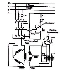
Rotor Resistance Starter - It consists of a series of resistors

Rotor Resistance Starter Circuit Diagram